


© 2019 Shri Vaari. All rights reserved. Website has been designed by GoodLore
 We build your dream
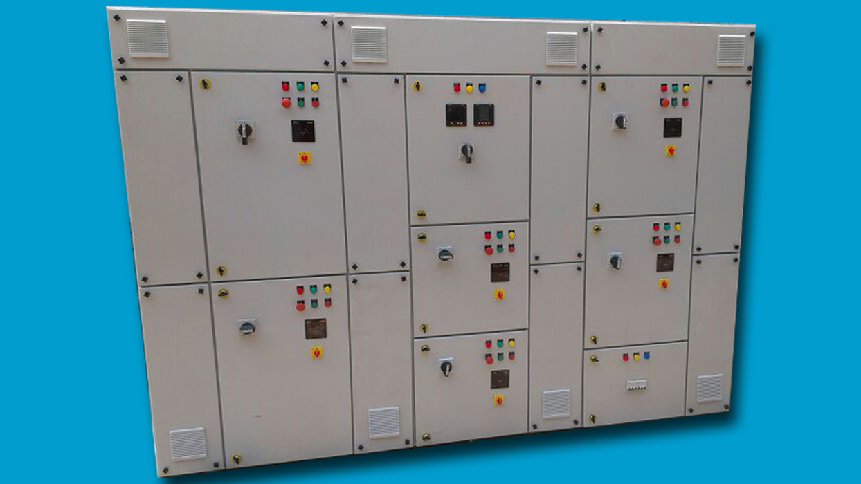
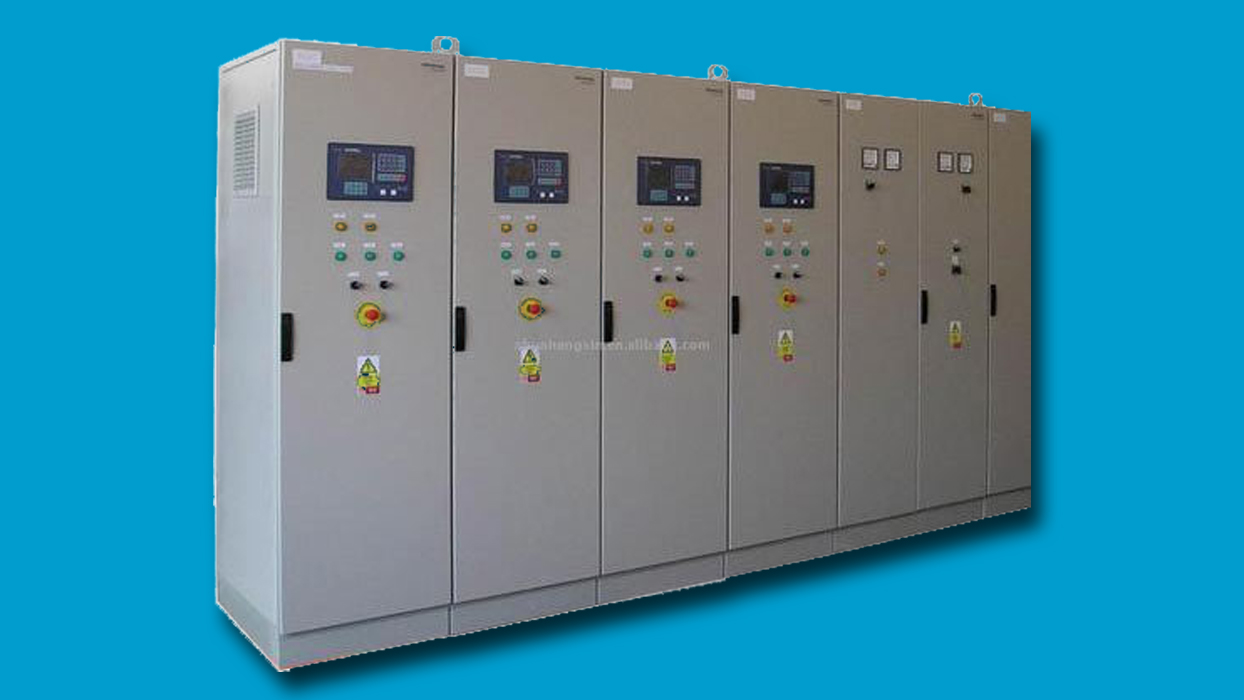
PLC - LT Panel
- A main circuit breaker complete with spring operated mechanism and operator independent is provided as the main protection for the automatic power factor correction equipment.
- All switching and protective devices and the connections are designed to carry continuously a current of 1.3 times the current, @ rated AC voltage and Frequency.
- An electronic reactive volt-ampere regulator will switch automatically on the required number of blocks according to load, so as to maintain the power factor at the set value indicated by the reactive power regulator. The regulator controls the opening and closing of the capacitor switching contactors. The range of the regulator is 0.8 to 0.99.
- Each contactor capacitor assembly is referred to as a capacitor step. The number of capacitor steps of switching operation is as per single line diagram.
- Each regulator is equipped with a device that automatically disconnects all connected capacitors in the event of a power failure. When power is restored, the capacitors are re- connected according to system reactive power needs, avoiding excessive capacitive power.
- An overload relay is fitted to trip the main incoming circuit breaker to the capacitor bank, and an out-of-balance current relay included to give visual / audible warning.
- Fail safe feature is incorporated to prevent leading power factor from every occurring.
- All contactors and switching devices is suitable for capacitor switching and is designed such that re striking during breaking operation cannot occur and heavy inrush current shall not cause contact welding during making operation.
- Local Display: LED or liquid-crystal digital type, mounted in door of enclosure, indicating
the following:
- Target and actual power factors accurate to plus or minus 1 percent of reading.
- Steps energized.
- Step reconnection delay.
- Real and reactive currents.
- Voltage total harmonic distortion.
- Alarm codes.
- System Alarms: Alarm relay and local display indication of the following conditions:
- Low power factor.
- Leading power factor.
- Frequency not detected.
- Overcurrent.
- Overvoltage.
- Over temperature.
- Excessive voltage total harmonic distortion.
- Capacitor overload.
- Loss of capacitance.
- Communication module -Optional
Company Presentation