


© 2019 Shri Vaari. All rights reserved. Website has been designed by GoodLore
 We build your dream
APFC - LT Panel
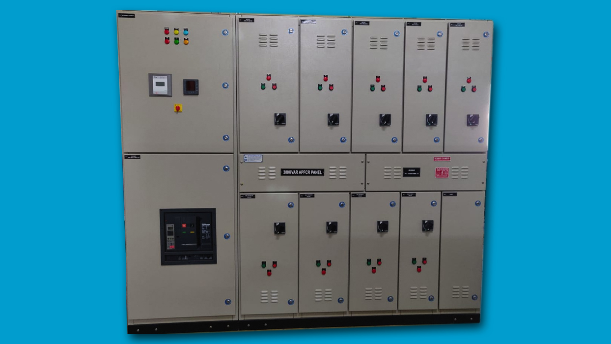
- The power capacitor are self-healing; metallised Polypropelene (MPP) type and completely resin moulded in hermetically sealed containers, naturally cooled, indoor type. PFC back are contactor based.
- Capacitors are designed, manufactured constructed and tested in accordance with relevant code.
- The power losses does not exceed 0.2 Watt / KVAR (or 0.4 watt / KVAR taking the discharge resistance into account).
- Every capacitor equipment are provided with a directly discharge device providing a discharge path without having a disconnecting switch, fuse cut-out, or series capacitor interposed.
- The discharge device reduces the residual voltage from the crest value of 660 volts to 50 volts or less within one minute after the capacitor disconnected from the source of supply.
- Facilities are provided for short-circuiting the capacitor terminals together and to earth before handling.
- When capacitors are switched off and on at very short intervals, arrangements are made so that, at the time of reapplication of the voltage, the voltage at the terminals of the capacitor are not more than 10% of the rated r.m.s. Voltage.
- Each unit of capacitance are a 3 phase balanced load and controlled by a adequately rated triple pole contactor.
- Each bank of capacitor units are provided with an incoming bus bar chamber rated for the total load of the maximum number of capacitor units. Units are interconnected by an enclosed all insulated Aluminium/ bus bar system.
- Each unit of capacitance in a bank are provided with a red pilot light to indicate when the capacitor is operational.
- Acceptable, harmonic current handling capacity (for p=7% de-tuned reactor):
- I1 = 1.06 Ic ( fundamental current )
- I3 = 1.04 x I1 (3rd harmonic)
- I5 = 1.31 x I1 (5th harmonic)
- I7 = 1.13 x I1 ( 7th harmonic)
- I max =1.5 x I
Company Presentation